

A Proposal to Modify the Low-Pressure Air System Cooling Arrangement aboard Halifax-class Frigates
- MS Nathanial R. Frid
- Jun 13, 2022
- 7 min read
[*Adapted from an October 2021 Marine Systems Engineering Division Mar Tech Mechanic RQ-P2 course student Technical Service Paper.]
A number of Halifax-class frigates have experienced seawater flooding of their low-pressure air (LPA) system. The ingress was a result of the after air cooler on the LPA compressor failing, and the pressure of the seawater service (SWS) system used for cooling being higher than that of the LPA system. Due to the corrosive nature of sea water, the LPA systems had to be flushed, and downstream components refurbished at significant financial cost. In some cases, the flush and other work took more than six months to complete, during which time the ship was unable to sail and fulfill mission requirements. Two possible solutions for modifying this arrangement were investigated for course study purposes. The preferred one (Option A) uses an arrangement involving the freshwater chilled-water system main, while the other (Option B) employs the auxiliary seawater circulation (ASWC) system to cool the LPA system.
Current Configuration
LPA coolers use sea water from the SWS system operating at 12 bar, a pressure greater than that of the LPA system which operates at 8 bar. Sea water from the SWS main proceeds past the normally open primary isolation valve to a secondary isolation valve, which is also normally open to the pressure-regulating valve that has an isolation valve on either side. Pressure is reduced to 2 bar through the pressure-reducing valve, which is fitted with a bypass in the event of failure.
Sea water passes through the after air cooler, which is protected by two zinc anodes, to cool the compressed air. When the sea water exits the after cooler, it goes through the compressor oil cooler — protected by three zinc anodes — and then through a diaphragm isolation valve before discharging to the ASWC system. In the after engine room (AER), the LPA cooler discharge connects to the discharge side of the port controllable reversible pitch propeller (CRPP) cooler, and in the forward engine room (FER) it connects to the discharge side of the port engine space cooler.
Atmospheric pressure air drawn in from the citadel on three deck is compressed to 8 bar by the rotary vane compressor, then discharged to the after air cooler. As this occurs, the air passes through a paper water separator where bulk water droplets are removed and discharged to the inside machinery space (IMS) drain. The air is discharged to the dryer through a screw-down non-return valve (Figure 1), whose purpose is to prevent LP air from returning back through the compressor. In order for sea water to get into the LPA system, the sea water has to go through this valve at a greater pressure than the LPA system pressure. Possibilities of how this situation might have occurred are as follows:
The seawater discharge from the after cooler shares an overboard discharge with the port CRPP cooler in the AER, and with the port engine space cooler in the FER. If either of the overboard discharges were isolated, the after air cooler tubes could rupture, allowing sea water to enter the compressor air discharge ahead of the screw-down non-return valve, building pressure beyond 8 bar. With the LPA system pressure unable to keep the valve closed, sea water would discharge into the system.
If the seawater pressure-reducing valve failed to reduce the seawater pressure to 2 bar, the result would be the same as in paragraph 1.
Constant changes in the SWS system pressure require manual adjustments to the pressure regulator bypass valve. If the seawater pressure regulator bypass valve were opened, and not manually set to 2 bar, the result would again be the same as in paragraph 1.
The Problem and Criteria for Solution
The problem with using the current SWS system is that the supply pressure coming from the fire main is greater than the LPA system pressure that keeps the non-return valve closed when the compressor is not running. Sea water causes corrosion in the after cooler, which degrades the tubes that cool the compressed air. If the seawater pressure regulator fails, which it commonly does, or the return is shut, the weakened tubes can burst and pass sea water through the screw-down non-return valve into the LPA system.
In order to prevent seawater migration into the LPA system, and thereby eliminate the high cost of flushing the LPA system and refurbishing any corrosion damage downstream, the following considerations are offered:
The cooling medium supply pressure should be lower than the LPA system pressure to guard against accidental ingress;
The cooling medium could be prevented from entering the LPA system (i.e. by using a separate closed coolant supply system);
The cooling medium should be non-corrosive (i.e. using fresh water rather than salt water).

Figure 1. Screw-down non-return valve aboard a Halifax-class frigate
Option A – Changing to a Chilled-Water Cooling Medium
Option A investigated utilizing the chilled-water main. This system uses fresh water mixed with glycol and a rust inhibitor, and operates at a maximum pressure of 4 bar. Since the supply and return piping (Figure 2) runs over both LPA compressors, the chilled-water main could be connected to the inlet ahead of the second isolation valve (Figure 3) on the supply side, and to the oil cooler outlet isolation valve for the return (Figure 4). The current SWS supply line from the fire main would have to be removed and capped. The total cost of installation was estimated to be $28,800.

Figure 2. Chilled water supply and return.

Figure 3. Flex line to LPA compressor cooling.

Figure 4. Flex line to the chilled-water return main.
Option B – Changing to the ASWC System for Cooling
Option B investigated using the ASWC system, which would only require installation of an isolation valve and a hard copper line to the inlet of the secondary isolation valve. The SWS system supply line would still need to be removed and capped. However, the point where the new isolation valve would be placed differs for the two engine rooms: In the AER, it would be by the inlet of No. 2 chiller (Figure 5); and in the FER, it would be ahead of the inlet isolation valve for the port space cooler (Figure 6). No changes would be required for either of the returns from the LPA compressor oil coolers. Total cost of parts and labour would be the same as for Option A.

Figure 5. The auxiliary seawater circulation (ASWC) system supply in the after engine room.
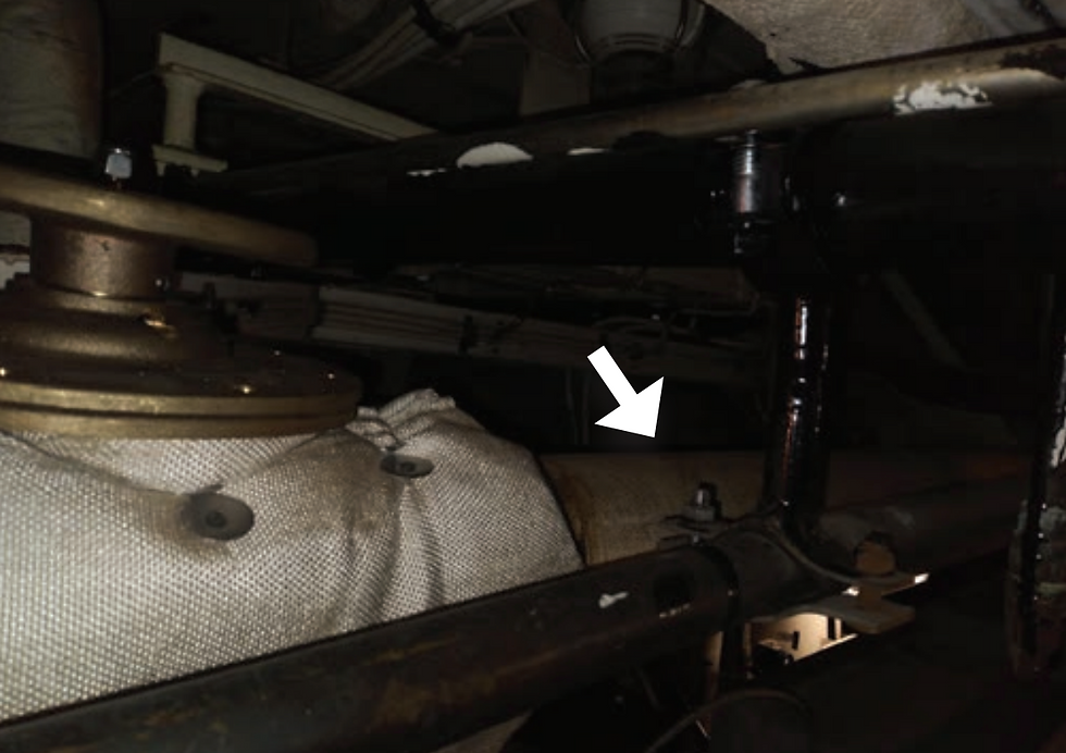
Figure 6. ASWC supply in the forward engine room.
Option Analysis
Option A (Preferred)
The Halifax-class frigates were initially fitted with four 85-ton chillers, which did not generate enough chilled-water capacity to meet the full cooling demand including the LPA coolers, hence the use of the SWS system for this purpose. However, the frigates today are fitted with four 114-ton chillers that are more than capable of servicing the LPA system.
There are a number of advantages to utilizing the chilled-water system. Having fresh water mixed with glycol and a rust inhibitor as the cooling medium, rather than sea water, will prevent corrosion to the LPA coolers, thereby increasing their life expectancy, and eliminating millions of dollars in unnecessary labour and parts costs to flush the system and refurbish corrosion-damaged components over the lifespan of the frigates. The RCN can also still use the spare coolers that are currently in the stores system.
Critically, the freshwater medium will not harm downstream components should it ever discharge into the LPA system. Due to the steady operating pressure of the chilled-water system being just 4 bar, the medium cannot normally force its way past the screw-down non-return valve that is kept shut by the higher 8-bar pressure of the LPA system, even when the compressor is not in use. The environmental impact if the oil cooler fails is also greatly reduced, since the chilled-water system is a closed system.
One small disadvantage of using the chilled-water main is that the seals in the coolers might not be compatible with glycol, and would therefore need to be replaced. This is heavily outweighed by the potential savings, and the reduced loss of ship availability.
Option B
The advantage of utilizing the ASWC is that only one portion of the LPA cooling system would need to be modified – the inlet. All other parts of the current arrangement, including the seawater discharge from the LPA compressor, would remain the same. Since the ASWC system operates at only 1.3 bar, the pressure-reducing valve could be fully bypassed without affecting the cooling to the LPA compressor. And because the system operates at a much lower pressure, sea water cannot push past the screw-down non-return valve to enter the LPA system if the after cooler fails, or if the seawater discharge of the compressor becomes plugged or isolated.
There are several disadvantages, however. The cooling medium is still sea water, which will cause corrosion if it somehow gets into the LPA system, and the ASWC system pressure can experience sudden drops when valves along its route are opened.
Summary and Recommendations
RCN ships have had a few instances of sea water migrating into the LPA system through failure of the after air cooler compressor, thereby allowing the higher pressure of the cooling seawater service to overpower the non-return valve normally kept shut by the lower pressure inside the LPA system. This has cost the RCN millions of dollars in flushes and repairs.
In this present study conducted for course purposes, the preferred solution (Option A) recommends that the chilled-water system, which uses fresh water infused with glycol and a rust inhibitor, be used in place of the SWS system to prevent degression of both the oil cooler and the after air cooler. Since the medium is at a lower pressure than the LPA system, the likelihood of it migrating into the LPA system is minimal, but should it do so, there would be no salt in the system to corrode components that interface with other vital systems, and a system flush would be much less labour-intensive as one involving sea water. There would be significantly less impact on ship mission readiness
It is therefore recommended that the following actions be taken:
Raise an Unsatisfactory Condition Report (UCR) concerning the SWS supply pressure being higher than the LPA system pressure;
Request that Fleet Maintenance Facility Cape Scott (FMFCS) Engineering design and trial a new configuration for chilled water use; and
Create a permanent Engineering Change (EC) for all Halifax-class ships. [The author has since submitted a temporary EC for evaluation regarding proposed changes to the LPA cooling arrangement in the forward engine room. It is currently being reviewed. – Editor]
Master Sailor Nathanial R. Frid is a Marine Engineering Technician, and Supplementary Maintenance Team supervisor with Fleet Maintenance Facility Cape Scott in Halifax, NS.


Comments